A Shot of Espressif: Using an Arduino to flash an Espressif ESP01s
Written on July 18th, 2022 by Sean Webster
Picture: Hummingbird hawk-moth at Beebalm
Getting back into the flow of things…
I swear, I’m not actively finding other things to do that aren’t my programming projects… That’s not quite true… I’ve planted out a vegetable garden, increased my blueberry patch, cut down and mulched some trees, started on my micro vinyard, finished installing an electric fence, and put a second deep box on my beehive since the last post about this project.
ESP-IDF plugin install for clion
ESP-IDF is the development framework for Espressif SoCs supported on Windows, Linux and macOS.
My favorite IDE is currently CLion, and if I didn’t get an account through work for free, I’d possibly buy it (the single developer license is ~$100 a year last I checked). However, VSCode is quickly catching up, so who can say what will be my favorite IDE when it’s time to renew my license.
Any ways, I digress. Jetbrains has made a nice video for integrating
UPDATE:08/01/2022
It has come to my attention trying to set this up, that the esp8266 is not a ESP32. They are both 32 bit micros. The video is still useful, though, but it is not exactly what I want.
The IDF can be found here (This is the ESP32 IDF)
The ESP8266 IDF can be found here
First some hardware setup…
So… a few years ago, I ordered some ESP-01ses. They sat around for a bit. Then a few years later I ordered some adapter boards. I had started to create a similar, more complex project, with larger scope, and more planning. I don’t remember why I dropped it, but I plan for this project to be a modular rebirth of that project.
The ESP01s is an 8-pin board with an ESP8266 on it, and oh boy are they cheap (can be had for as little as $2.39, even in the shortage!). It’s got 2.4 GHz wifi, serial, 2 gpios and an onboard LED.
The ESP-01s is only 8 pins, but it is easily flashable with a small set of components:
- ESP01 (I used a breakout board board)
- Arduino Uno (or similar)
- USB cable
- 2.2K Resistor
- 3.3K Resistor
- Breadboard
- Pushbutton
- Jumpers
Pin Outs
Hook up said components like so
Grounding the reset pin on the arduino configures it as a passthrough serial.
Grounding the GP0 pin on the ESP01s puts it into bootloader mode
The arduino serial voltage level is 5V, so we use a voltage divider to get to the 3.3V the ESP8266 uses
(You’d think TX->RX, right? I think one of my boards may be mislabeled)
| ESP01s | Arduino |
|---|---|
| GND | GND |
| VCC | 3.3V |
| CHPD | 3.3V |
| GP0 | GND |
| TXD | TX/D1 |
| RXD | RX/D0 |
| RST->Button | — |
| — | RST->GND |
Forgive my first KiCad schematic. My fridge does not have a magnetic front, so this is the closest place I have to post it

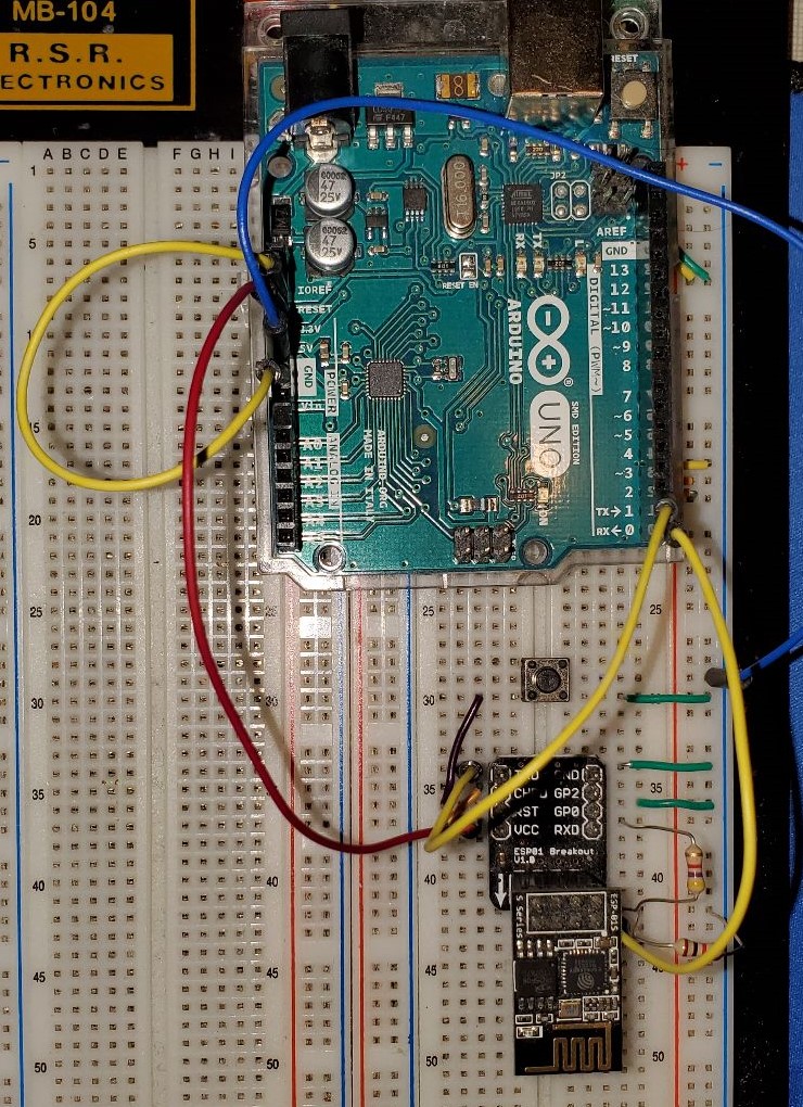
Here is a bad picture of my setup